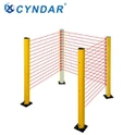
At present, in the production line of industrial equipment, in order to protect the personal safety of operators, safety carpets are installed in hazardous areas. When workers enter the safety carpet in the hazardous area, the equipment will stop working to prevent mechanical equipment from harming the human body. However, in actual application of safety carpets, due to the failure of the safety carpet itself, when workers enter the dangerous area, the safety carpet cannot send an effective shutdown signal, and the equipment cannot be shut down in time, which may cause serious safety accidents. In order to avoid the occurrence of safety accidents caused by the failure of the safety carpet, a special safety relay for the safety carpet is designed to monitor it.
Technical realization elements:
The main purpose of the utility model is to propose a safety relay for monitoring the safety carpet, which aims to solve the existing technical problems.
In order to achieve the above purpose, the safety relay for monitoring the safety carpet proposed by the present invention includes a power module, a channel detection circuit, a carpet trigger signal input system, a start signal input circuit, a channel short-circuit control system, a safety output system, and a forced-oriented relay module. The safety output contact is composed of two sets of forced-oriented relay contacts in series, which are used to control the external load power circuit; the carpet trigger signal input system is used to receive external trigger signals and send the signals to the channel short-circuit control system The channel short circuit control system is used to control the on and off of the power supply of the forced guidance relay module. When the stop signal is received, the forced guidance relay module is short-circuited by the short circuit control system, the coil of the forced guidance relay module is de-energized, and the safety output system is cut off. open.
Further, the power module includes a power input circuit, an overcurrent protection circuit, a filter rectifier circuit, and a power detection system. The power input circuit is used to receive power; the overcurrent protection circuit is used to protect the circuit; and the filter The rectifier circuit is used to modulate the external input power; the power detection system is used to detect whether the external power supply is normal to provide power to the safety relay.
Further, the power input circuit is electrically connected with a 24VDC power supply.
Further, the forced guidance relay module includes a forced guidance relay and a self-locking circuit. The forced guidance relay is used to provide contact switches; the self-locking circuit is used to maintain the forced guidance relay after receiving the start signal. Always in working condition.
Further, the start signal input circuit includes an electrical-optical-electric conversion system for isolating input and output electrical signals.
Adopting the technical scheme of the utility model has the following beneficial effects: the technical scheme of the utility model has simple structure and convenient operation. The overall circuit structure adopts redundant design ideas, and real-time detection of two sets of channels of the safety carpet is carried out to the greatest extent. Improved the probability of safety accidents caused by the failure of the safety mat itself. In the safety circuit design, the two sets of channels of the safety carpet are monitored in real time through the safety relay, the hazard signal triggered by the safety mat is collected, and the hazard signal is fed back to the controller or AC contactor through the safety output contact of the safety relay, and the equipment is realized Safe shutdown.
Description of the drawings
In order to more clearly describe the technical solutions in the embodiments of the present utility model or the prior art, the following will briefly introduce the drawings that need to be used in the description of the embodiments or the prior art. Obviously, the drawings in the following description These are just some embodiments of the present invention. For those of ordinary skill in the art, without creative work, other drawings can be obtained based on the structure shown in these drawings.
Figure 1 is a schematic diagram of the overall frame structure of a safety relay for monitoring safety carpets according to an embodiment of the utility model;
Figure 2 is a schematic circuit diagram of a safety relay for monitoring a safety carpet according to an embodiment of the present invention.
The realization of the purpose, functional characteristics and advantages of the utility model will be further described in conjunction with the embodiments and with reference to the accompanying drawings.
detailed description
The following will clearly and completely describe the technical solutions in the embodiments of the present utility model with reference to the accompanying drawings in the embodiments of the present utility model. Obviously, the described embodiments are only a part of the embodiments of the present utility model, rather than all of them. Examples. Based on the embodiments of the present utility model, all other embodiments obtained by those of ordinary skill in the art without creative work shall fall within the protection scope of the present utility model.
It should be noted that all the directional indications (such as up, down, left, right, front, back...) in the embodiments of the present invention are only used to explain between the components in a specific posture (as shown in the drawings). If the specific posture changes, the directional indication will also change accordingly.
In addition, the technical solutions between the various embodiments can be combined with each other, but it must be based on what can be achieved by a person of ordinary skill in the art. When the combination of technical solutions is contradictory or cannot be achieved, it should be considered that such a combination of technical solutions does not exist. , Is not within the scope of protection required by the utility model.
The utility model provides a safety relay for monitoring safety carpets.
As shown in Figures 1 and 2, in an embodiment of the present invention, the safety relay for monitoring the safety carpet includes a power supply module 10, a channel detection circuit 20, a carpet trigger signal input system 30, a start signal input circuit 40, and a channel short circuit. A control system 50, a safety output system 70, and a forced oriented relay module 60, the safety output system 70 is connected to the forced oriented relay module 60, and the safety output system 70 is composed of two sets of forced oriented relay contacts in series. For controlling the external load power circuit; the carpet trigger signal input system 30 is used to receive an external trigger signal, and send the signal to the channel short-circuit control system 50, the channel short-circuit control system 50 is used to control the power supply of the forced-oriented relay module 60 When the stop signal is received, the forced directional relay module 60 is short-circuited by the channel short circuit control system 50, the coil of the forced directional relay module 60 is de-energized, and the safety output system 70 is disconnected.
Specifically, the power module 10 includes a power input circuit 101, an overcurrent protection circuit 102, a filter rectifier circuit 103, a power detection system 104, and a power input terminal 105. The power input circuit 101 is used to receive power; The protection circuit 102 is used to protect the circuit; the filter and rectifier circuit 103 is used to modulate the external input power; the power detection system 104 is used to detect whether the external power supply is normal to provide power to the safety relay.
Specifically, the power input circuit 101 is electrically connected to a 24VDC power supply.
Specifically, the forced guidance relay module 60 includes a forced guidance relay (K1, K2) and a self-locking circuit, the forced guidance relay is used to provide a contact switch; the self-locking circuit is used to force the guidance relay to receive a start signal After that, maintain the forced guidance relay always in working condition.
Specifically, the start signal input circuit 40 includes an electrical-optical-electric conversion system for isolating input and output electrical signals.
Specifically, the working principle of the safety relay is: the power supply circuit of the safety relay is turned on, the power detection system starts to work, and the power indicator light is on under normal conditions. Start the safety relay (can be started automatically or manually), the coils of the forced oriented relay module in the safety relay are energized at the same time, and the two sets of self-locking circuits are activated, so that the two groups of forced oriented relay modules work stably and continuously, and the interlock circuit is also activated to prevent Continue to start the safety relay to protect the starting circuit. At the same time, the signal input channel indicator circuit is activated. When the input channel is normal, the signal indicator light is on. When the carpet trigger signal receives the trigger signal, the channel short-circuit control module is activated, and the two sets of signal input channels are short-circuited, the guide relay module is forced to lose power, and the safety output contact is disconnected to realize the function of safe shutdown. When the safety mat fails, the channel detection system of the safety relay will diagnose the fault signal. At this time, the forced-oriented relay module of the safety relay will not be activated, and the channel indicator will be off, so the safety output contact will always remain open. The safety relay will only be activated when the fault of the carpet is removed.
The above descriptions are only preferred embodiments of the utility model, and do not limit the scope of the utility model's patents. Any equivalent structural transformation made by using the contents of the utility model description and drawings under the utility model concept of the utility model is not intended to limit the scope of the utility model. Or directly/indirectly used in other related technical fields are included in the scope of patent protection of the present utility model.